Maintenance Business Process For A Gold Mine.
Disclaimer.
This article draws on general gold mining industry knowledge, common CMMS principles and established maintenance management practices used across mining operations, supplemented by insights from the author.
It outlines broadly accepted frameworks rather than site‑specific guidance. Actual implementation requirements will vary significantly depending on mine type (open pit vs. underground), ore characteristics, processing technology, regulatory obligations, geographic conditions and organizational maturity.
This article does not constitute professional consulting advice. The opinions, views, thoughts and ideas expressed are those of the author only.
Mining organizations should engage qualified maintenance professionals and conduct detailed site assessments before adopting any maintenance business process. All references to technologies, systems, or procedures should be validated against current industry standards and manufacturer specifications.
Article Summary.
It would be fair to say that launching a new gold mining operation would demand a disciplined, integrated approach to maintenance.
A quality maintenance business process must coordinate multiple work streams and ensure seamless interaction between operations, maintenance, engineering and supply chain teams.
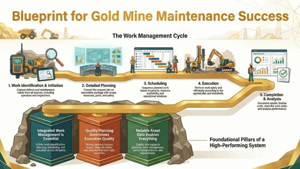
This article outlines a structured framework built around eight essential process areas: work identification and initiation, detailed planning, scheduling, execution, performance monitoring, shutdown management, asset data management and continuous improvement.
The framework reflects proven methodologies used in operating gold mines and emphasizes the importance of clear role definitions, standardized workflows and robust CMMS capability.
Effective implementation requires unambiguous approval pathways, well‑designed KPIs and consistent understanding of responsibilities across the entire work management cycle.
A successful maintenance process must balance safety, equipment reliability, cost control and production targets, while remaining flexible enough to manage the unique challenges of gold mining, such as ore variability, environmental constraints and remote‑site logistics.
Top 5 Takeaways.
1. Integrated Work Management System: A gold mine’s maintenance function must operate as a fully integrated system that links work identification, planning, scheduling, execution and closeout. Clear handoffs between operations, maintenance, engineering and supply chain functions are essential for reliability and efficiency.
2. Role Clarity Is Essential: Clear, explicit responsibility definitions, from tradespersons to senior leaders, are critical. Accountability tools such as RACI matrices help eliminate ambiguity, streamline decision‑making and ensure consistent work execution.
3. Planning Quality Determines Execution Quality: High‑quality planning, including job steps, resource requirements, materials, tooling, safety analysis and work instructions, must be completed before work is scheduled. Strong planning reduces delays, improves safety and increases the likelihood of first‑time‑right execution.
4. Shutdown Management Requires a Dedicated Process: Major shutdowns demand specialized planning and control. Critical path analysis, risk assessments, scope freeze protocols and rigorous progress tracking must be managed separately from routine maintenance to protect production and safety outcomes.
5. Asset Data Integrity Enables Everything: Reliable equipment hierarchies, bills of materials, maintenance strategies and work history records form the backbone of effective maintenance. Quality data supports planning, parts management, performance analysis and continuous improvement across the mine’s lifecycle.
Table of Contents.
1. Introduction
2. Process Architecture Overview
o 2.1 Core Process Components
o 2.2 Integration Requirements
o 2.3 Critical Success Factors
3. Work Identification and Initiation
o 3.1 Work Request Sources
o 3.2 Work Classification System
o 3.3 Work Order Status Progression
o 3.4 Immediate Work Process
4. Work Planning Process
o 4.1 Planning Scope and Objectives
o 4.2 Job Plan Development
o 4.3 Resource Identification
o 4.4 Material Management Integration
5. Work Scheduling Process
o 5.1 Backlog Management
o 5.2 Weekly Scheduling Methodology
o 5.3 Daily Scheduling Process
6. Work Execution and Completion
o 6.1 Pre-Work Requirements
o 6.2 Execution Control
o 6.3 Completion Standards
o 6.4 Work History Documentation
7. Shutdown Management
o 7.1 Shutdown Planning Framework
o 7.2 Scope Definition and Freeze
o 7.3 Critical Path Management
o 7.4 Progress Tracking
8. Preventive Maintenance Management
o 8.1 PM Strategy Development
o 8.2 Work Order Generation
o 8.3 Strategy Optimization
9. Asset and Master Data Management
o 9.1 Equipment Hierarchy
o 9.2 Bills of Materials
o 9.3 Maintenance Plans
10. Performance Management
o 10.1 Key Performance Indicators
o 10.2 Planning Performance Metrics
11. Organizational Roles and Responsibilities
o 11.1 Maintenance Management Structure
o 11.2 Planning and Scheduling Roles
o 11.3 Execution Roles
12. Implementation Considerations
o 12.1 CMMS Configuration
o 12.2 Training Requirements
o 12.3 Process Documentation
13.0 Conclusion.
14.0 Explore More Content Connected to This Topic On This Website.
15.0 Bibliography.
1.0 Introduction.
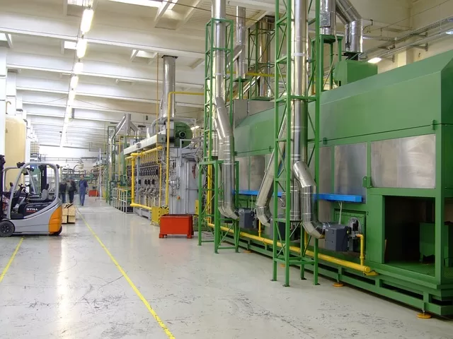
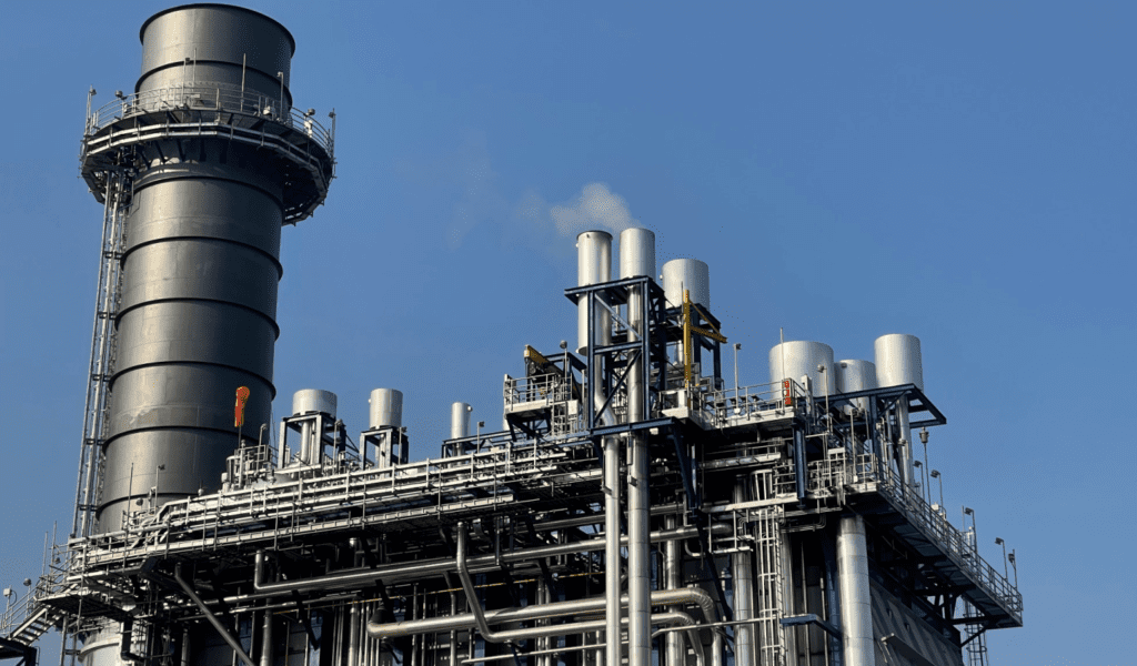
Gold mining operations present a uniquely demanding maintenance environment. Unlike many industrial settings, a gold mine combines heavy mobile fleets, complex fixed‑plant processing circuits and continuous‑operation infrastructure that must perform reliably under harsh and variable conditions.
Processing facilities typically include crushing and grinding systems, flotation or gravity circuits, leaching and adsorption stages (CIP/CIL), electrowinning cells and extensive utilities.
Underground mines add ventilation, pumping, ground support and mobile equipment maintenance complexity, while open‑pit operations rely on ultra‑class haul trucks, excavators and drilling equipment exposed to dust, vibration and extreme weather.
A maintenance business process for such an operation must support 24/7 production with minimal unplanned downtime while managing a wide range of operational realities:
1. Equipment criticality: Single‑point failures in crushers, mills, or pumping systems can halt production entirely.
2. Environmental and regulatory constraints: Tailings, cyanide handling, water treatment and statutory inspections require strict compliance and continuous operation.
3. Remote‑site logistics: Long supply chains, limited local technical support and FIFO workforce models increase planning and scheduling complexity.
4. Ore variability: Changes in ore hardness and mineralogy alter equipment loading, accelerating wear and complicating predictive maintenance.
5. Capital intensity: High‑value assets demand disciplined lifecycle management to protect return on investment.
A high‑quality maintenance business process provides the structure to manage these challenges systematically.
It establishes standardized workflows, clear accountability, integrated planning and scheduling and continuous performance feedback.
When executed well, the process becomes the backbone of operational reliability, ensuring that equipment is maintained safely, efficiently and in alignment with production objectives.
1.1 Below is a categorized list of typical gold mine processing equipment.
Stage 1: ROM Pad & Primary Crushing – Preparing the Ore.
Objective: Break large ore into manageable size.
1. ROM Bin / Dump Pocket.
2. Static Grizzly.
3. Rock Breaker (Pedestal Boom System).
4. Apron Feeder / Vibrating Grizzly Feeder (VGF).
5. Primary Jaw Crusher or Gyratory Crusher.
6. Dust Extraction & Suppression Systems.
7. Metal Detectors & Tramp Iron Magnets.
8. Belt Weighers (Weightometers).
9. Primary Crusher Discharge Conveyor.
10. Emergency Stockpile / Surge Bin.
Stage 2: Secondary Crushing, Screening & Grinding.
Objective: Reduce ore to fine slurry for gold liberation.
1. Secondary Cone Crushers.
2. Tertiary Cone Crushers.
3. Vibrating Screens (Single/Double/Triple Deck).
4. Screen Undersize & Oversize Conveyors.
5. Transfer Towers & Chutes.
6. SAG Mill.
7. Ball Mill.
8. Mill Lube Systems.
9. Mill Discharge Pumps.
10. Hydrocyclone Cluster.
11. Mill Trommel Screen.
12. Pebble Crusher (if SAG circuit includes scats).
13. Mill Recycle Conveyors.
14. Mill Feed Bins.
15. Process Water Pumps & Storage Tanks.
Stage 3: Leaching & Adsorption – CIL/CIP.
Objective: Dissolve gold and adsorb onto carbon.
1. Leach Tanks (CIL/CIP Tanks).
2. High‑Shear Cyanide Mixing System.
3. Oxygen Sparging System / Oxygen Plant (PSA or LOX).
4. Agitators & Gearboxes.
5. Inter‑stage Screens / Carbon Safety Screens.
6. Carbon Transfer Pumps.
7. Carbon Recovery Screens.
8. Carbon Attrition Mills (optional).
9. Slurry Pumps & Pipelines.
10. pH Control System (Lime Slakers, Lime Dosing Pumps).
11. Cyanide Dosing System.
12. DO (Dissolved Oxygen) Sensors.
13. Carbon Storage & Handling Equipment.
Stage 4: Gold Recovery – Elution, Regeneration & Electrowinning.
Objective: Strip gold from carbon and plate it as metal.
1. Elution Column (Zadra, AARL, or Pressure Zadra).
2. Elution Heaters / Heat Exchangers.
3. Elution Circulation Pumps.
4. Acid Wash Column.
5. Carbon Regeneration Kiln (Rotary Kiln or Vertical Kiln).
6. Carbon Quench Tank.
7. Electrowinning Cells (EW Cells).
8. Rectifiers (DC Power Supply).
9. Sludge Filters / Filter Press.
10. Elution Water Heaters & Boilers.
11. Safety Showers & Cyanide Emergency Systems.
Stage 5: Gold Room – Smelting & Doré (High Value Alloy) Production.
Doré is a high‑value alloy, typically containing:
- 70–95% gold.
- 5–20% silver.
- Small traces of other metals or impurities.
The exact composition depends on the ore body and the plant’s recovery process.
In a lot of cases, Gold Mines don’t refine gold to 99.99% purity on site.
Instead, they:
1. Recover gold onto steel wool (electrowinning).
2. Smelt it with fluxes.
3. Pour it into bars.
4. Ship those bars to an accredited refinery.
The refinery then separates and purifies the metals to produce market‑grade bullion.
What a doré bar looks like.
Doré bars are:
- Rough‑surfaced.
- Matte or dull gold in colour.
- Stamped with weight, purity estimate, and a unique ID.
They are extremely valuable but not yet “refined gold.”
Doré will be eventually be refined into 99.99% bullion.
Objective: Produce doré bars safely and securely.
1. Steel Wool Filters.
2. Drying Oven.
3. Induction or Gas‑Fired Smelting Furnace.
4. Flux Storage & Dosing Equipment.
5. Crucibles (Graphite, Clay‑Graphite).
6. Pouring Moulds.
7. Mould Cooling Rack / Trolley.
8. Quench Bath.
9. Bar Cleaning & Polishing Tools.
10. Precision Weighing Scales.
11. Security Cameras & Access Control.
12. Vault / Safe Storage.
13. Fire Suppression Systems.
Stage 6: Tailings & Water Management.
Objective: Manage waste and recycle water.
1. Tailings Thickener.
2. Thickener Rakes & Drive System.
3. Flocculant Mixing & Dosing System.
4. Tailings Pumps & Pipelines.
5. Tailings Storage Facility (TSF) Monitoring Systems.
6. Cyanide Detoxification Plant (INCO SO₂/Air, Caro’s Acid, etc.).
7. Return Water Pumps.
8. Water Polishing Filters.
9. Stormwater Diversion Systems.
Supporting Systems (Critical Across All Stages).
1. Process Control & Instrumentation:
a) SCADA / DCS Control System.
b) PLC Panels.
c) Flow, Level, Pressure & Density Instruments.
d) Online Analyzers (Cyanide, pH, DO, Carbon Concentration).
e) CCTV for plant monitoring.
2. Reagent Handling & Storage:
a) Cyanide Storage Tanks & Unloading Systems.
b) Lime Silos & Slakers.
c) Flocculant Mixing Plants.
d) Hydrochloric Acid Tanks.
e) Caustic Soda Tanks.
f) Oxygen Storage (LOX tanks or PSA plant).
3. Sampling & Metallurgical Equipment:
a) Automatic Samplers (Slurry & Solution).
b) Sample Preparation Equipment (Jaw Crusher, Pulveriser).
c) Fire Assay Furnaces.
d) AAS or ICP Units.
e) Carbon Activity Testing Equipment.
f) Bottle Roll Test Equipment.
4. Utilities & Infrastructure:
a) Compressed Air System.
b) Power Distribution (Transformers, MCCs, Switchrooms).
c) Backup Generators.
d) Workshops & Tooling.
e) Lubrication Storage & Dispensing Systems.
f) Mobile Equipment (Loaders, Telehandlers, Forklifts).
g) Laboratory Ventilation & Fume Extraction.
5. Safety & Environmental Systems:
a) Gas Detection (H₂S, CO, O₂, Cyanide).
b) Emergency Showers & Eyewash Stations.
c) Fire Hydrants & Sprinkler Systems.
d) Spill Containment Bunds.
e) Dust Extraction Units.
f) Noise Control Barriers.
Optional / Ore‑Specific Circuits.
For plants treating complex or refractory ores:
1. Gravity Recovery Circuit:
a) Knelson or Falcon Concentrators.
b) Shaking Tables.
c) Intensive Leach Reactor (ILR).
2. Refractory Ore Treatment:
a) Pressure Oxidation (Autoclave).
b) Roaster.
c) Bio‑Oxidation Reactors (BIOX).
d) Ultra‑Fine Grinding Mills (IsaMill, Stirred Mills).
2.0 Process Architecture Overview.
A gold mine’s maintenance business process must operate as a cohesive, interconnected system rather than a collection of isolated activities.
Reliability emerges when every workflow, from defect identification to shutdown execution, functions predictably, transparently and in alignment with production objectives.
The process architecture described in this section provides a structured foundation for consistent execution, clear accountability and continuous improvement across the entire maintenance lifecycle.
2.1 Core Process Components.
The maintenance process is built around several integrated workflows that together form the backbone of operational reliability. Each workflow has distinct objectives, but all must function in harmony to support safe, efficient and predictable maintenance delivery.
2.1.1 Work Management Cycle.
1. Work identification: Capture defects and maintenance needs from all sources.
2. Work review: Validate necessity, priority and feasibility.
3. Detailed planning: Define scope, resources, materials, methods and safety requirements.
4. Scheduling: Sequence work based on priority, resource availability and operational windows.
5. Execution: Perform work safely and efficiently.
6. Completion: Document results, update records and identify follow‑up needs.
7. Analysis: Evaluate performance and identify improvement opportunities.
2.1.2 Preventive Maintenance Process.
1. Strategy development: Define maintenance tactics based on criticality and failure modes.
2. Automated work order generation: Trigger PM tasks by time or meter.
3. PM execution: Perform inspections and routine tasks.
4. Strategy refinement: Adjust based on performance trends and failure analysis.
2.1.3 Shutdown Management Process.
1. Long‑term shutdown planning: Identify major events and required lead times.
2. Scope development: Define, validate and freeze shutdown work.
3. Critical path scheduling: Optimize sequencing and resource allocation.
4. Execution control: Track progress in real time.
5. Post‑shutdown review: Capture lessons learned and improvement actions.
2.1.4 Master Data Management Process.
1. Equipment hierarchy: Maintain structured, accurate asset registers.
2. Bills of materials: Ensure complete and validated spare parts lists.
3. Maintenance plans: Define PM tasks, frequencies and triggers.
4. Document control: Manage procedures, drawings and revisions.
2.2 Integration Requirements.
Maintenance cannot operate effectively in isolation. High‑performing mines rely on tight cross‑functional integration, ensuring that information, decisions and responsibilities flow seamlessly between departments.
2.2.1 Maintenance–Operations Interface.
1. Defect identification and work request initiation.
2. Production schedules and equipment availability windows.
3. Equipment status updates and planned outage coordination.
4. Joint scheduling meetings to align priorities.
5. Shared accountability for equipment reliability.
2.2.2 Maintenance–Supply Chain Interface.
1. Material requirement identification with appropriate lead times.
2. Procurement and delivery coordination for planned work.
3. Inventory management for critical spares.
4. Material returns and rebuildable processes.
5. Cost tracking and procurement approvals.
2.2.3 Maintenance–Engineering Interface.
1. Technical specifications for new installations.
2. Failure analysis support and improvement initiatives.
3. Performance data feedback from maintenance.
4. Strategy development for new or modified equipment.
5. Technical review of maintenance plans and procedures.
2.3 Critical Success Factors.
Several foundational elements determine whether a maintenance process will function reliably and consistently.
1. Process documentation: Clear workflows, decision points and approval pathways eliminate ambiguity.
2. Role clarity: RACI‑based responsibility definitions prevent gaps and overlaps.
3. System support: A well‑configured CMMS enforces process discipline and provides visibility.
4. Training and competency: Personnel must understand both the process and their role within it.
5. Performance measurement: KPIs provide feedback and drive accountability.
6. Management commitment: Leaders must reinforce process adherence and consequences for deviation.
7. Continuous improvement: Regular reviews ensure the process evolves with operational needs.
3.0 Work Identification and Initiation.
A high‑performing maintenance system begins with consistent, accurate and timely identification of work.
In a gold mining environment, where equipment operates continuously under variable loads and harsh conditions, the ability to capture defects early is essential for preventing failures, protecting production and maintaining safe operations.
This section outlines the structured mechanisms through which maintenance needs are identified, classified and initiated into the work management cycle.
3.1 Work Request Sources.
Maintenance work originates from multiple channels, each contributing essential visibility into equipment condition. A robust process ensures that all sources are captured, validated and routed into the CMMS without delay.
3.1.1 Operator‑Identified Defects.
Operators are the first line of defence in detecting abnormal conditions. Typical triggers include:
1. Abnormal operating behaviour such as noise, vibration, temperature spikes, or erratic performance.
2. Throughput or quality degradation indicating emerging equipment issues.
3. Visible damage or deterioration including leaks, cracks, corrosion, or loose components.
4. Safety or environmental concerns requiring corrective action.
5. Near‑miss events that highlight latent equipment risks.
Operators should have simple, reliable mechanisms to submit requests, such as CMMS terminals, mobile apps, radio communication, or structured paper forms.
3.1.2 Preventive Maintenance Inspections.
Routine inspections and condition‑based monitoring generate a significant portion of corrective work:
1. Wear and corrosion findings from PM tasks.
2. Predictive maintenance alerts (vibration, thermography, oil analysis).
3. Condition monitoring system alarms.
4. Statutory inspection requirements for pressure vessels, lifting equipment and electrical systems.
3.1.3 Engineering Recommendations.
Engineering inputs often drive reliability improvements and long‑term asset health:
1. Design modifications to improve performance.
2. Equipment upgrades or replacements.
3. Project‑related maintenance work.
4. Root cause analysis actions.
3.1.4 Maintenance‑Identified Work.
During execution, maintainers frequently uncover additional issues:
1. Follow‑up work from incomplete or temporary repairs.
2. Defects discovered during jobs.
3. Backlog reviews identifying overdue or deferred work.
4. Asset integrity program findings.
3.1.5 External Drivers.
Some work originates from outside the operation:
1. Regulatory compliance requirements.
2. Environmental permit conditions.
3. Insurance inspections.
4. OEM service bulletins.
3.2 Work Classification System.
Once a work request is submitted, it must be classified to determine the appropriate handling pathway.
Clear classification ensures that urgent issues receive immediate attention while planned work follows the full planning and scheduling cycle.
3.2.1 Priority 0 – Immediate.
Triggered by:
1. Production‑stopping breakdowns.
2. Critical safety hazards.
3. Environmental incidents.
4. Equipment unsafe to operate.
Process: Work bypasses normal planning and is executed immediately under supervisor control. A work order is created concurrently to capture cost and history.
3.2.2 Priority 1 – Urgent.
Triggered by:
1. Defects requiring action within the current week.
2. Degradation likely to cause failure soon.
3. Safety concerns not requiring shutdown.
Process: Fast‑tracked planning and insertion into the current schedule.
3.2.3 Priority 2 – Important.
Triggered by:
1. Significant defects needing timely correction.
2. Reliability or efficiency improvements.
Process: Full planning cycle; scheduled within 4–8 weeks.
3.2.4 Priority 3 – By Due Date.
Triggered by:
1. Preventive maintenance tasks.
2. Compliance inspections.
3. Future‑dated work.
Process: Full planning; scheduled to meet due dates.
3.2.5 Priority 4 – Shutdown.
Triggered by:
1. Work requiring major outages.
2. Intrusive inspections or overhauls.
3. Modifications needing extended downtime.
Process: Added to shutdown backlog and managed through shutdown planning cycles.
3.3 Work Order Status Progression.
A disciplined status progression provides transparency, process control and predictable workflow movement. Each status represents a clear stage in the work lifecycle:
1. NEW – Request created; awaiting review
2. WSU – Supervisor review for urgent work
3. WPL – Assigned to planner; planning in progress
4. WSC – Planning complete; ready for scheduling
5. WSP – Approved for scheduling; in ready backlog
6. IPR – Scheduled for execution in current period
7. IPC – Work started but carried over
8. COM – Physical work complete; awaiting documentation
9. TEC – Technically complete; costs and history finalized
10. CLS – Fully closed; available for reporting
This progression ensures that work flows predictably from identification to closure, with clear accountability at each stage.
3.4 Immediate Work Process.
Priority 0 work requires a streamlined, controlled response to restore safe operation or production as quickly as possible.
1. Process Steps
o Notification: Operations alerts maintenance of failure or hazard.
o Assessment: Supervisor determines required response.
o Resource mobilization: Assign trades and equipment.
o Safety preparation: Field‑level risk assessment, permits, isolations.
o Execution: Perform minimum work to restore function.
o Documentation: Create work order and record actual.
o Follow‑up: Raise planned work for permanent repair.
2. Key Controls
o Work order creation is mandatory to capture cost and history.
o Operations must prepare equipment (isolation, cleaning, access).
o Supervisor approval required for material purchases above limits.
o Follow‑up work orders ensure temporary repairs are addressed.
4.0 Work Planning Process.
The purpose of planning is to convert a work request into a complete, executable job package.
A well‑planned job minimizes uncertainty, reduces downtime and ensures that tradespeople spend their time executing work, not searching for parts, tools, or instructions.
Planning objectives include:
1. Defining complete work scope including all tasks required to restore equipment to the required condition.
2. Identifying labor resources by trade, skill level and estimated hours.
3. Listing all materials and parts with correct specifications and quantities.
4. Specifying tools, equipment and services such as scaffolding, lifting devices, or specialist contractors.
5. Developing a job hazard analysis that identifies risks and required controls.
6. Documenting work sequence and methods through clear work instructions.
7. Estimating realistic durations that account for access, coordination and constraints.
8. Validating material availability and identifying long‑lead procurement items.
Typical planning effort guidelines:
1. Simple PM tasks: 15–30 minutes.
2. Standard corrective work: 1–2 hours.
3. Complex overhauls: 4–8 hours.
4. Major projects: Multiple days with engineering involvement.
High‑quality planning reduces rework, improves safety and increases the likelihood of first‑time‑right execution.
4.1 Job Plan Development.
A structured methodology ensures consistency and completeness in job plan development.
4.1.1 Review Existing Information.
Planners begin by gathering all relevant background information:
1. Equipment manuals and technical documentation.
2. Previous work orders for similar failures.
3. Equipment history and recurring issues.
4. Maintenance strategies and standard repair approaches.
5. OEM service recommendations.
4.1.2 Conduct Site Assessment (for complex or unfamiliar work).
A field assessment validates assumptions and identifies constraints:
1. Confirm failure mode and required scope.
2. Verify access, isolation points and work area conditions.
3. Identify adjacent equipment requiring protection.
4. Capture photos for clarity.
5. Consult with operators and maintainers familiar with the asset.
4.1.3 Develop Work Steps (Operations).
Work is broken into clear, measurable operations:
1. Preparation (scaffolding, barricading, tool staging).
2. Isolation, lock‑out, tag‑out and verification.
3. Dismantling, removal and cleaning.
4. Inspection, measurement and NDT testing.
5. Replacement, assembly and alignment.
6. Testing, commissioning and restoration.
7. Cleanup and area reinstatement.
4.14 Assign Resources to Operations.
For each operation, planners specify:
1. Required trade or work center.
2. Number of personnel.
3. Estimated hours per person.
4. Sequence and parallel work relationships.
4.1.5 Identify Materials.
Material requirements must be precise and complete:
1. Stock items: Use catalog numbers and quantities.
2. Non‑stock consumables: Provide descriptions and estimated costs.
3. Direct purchases: Include specifications and delivery requirements.
Materials should be linked to specific operations to support accurate tracking.
4.1.6 Identify Equipment and Services.
Planners determine additional requirements such as:
1. Cranes, forklifts and elevated work platforms.
2. Specialist tools (alignment equipment, torque tools, test instruments).
3. Scaffolding specifications.
4. External services (NDT, machining, specialist contractors).
5. Hire equipment with required lead times.
4.1.7 Develop or Attach Work Instructions.
Instructions may include:
1. Standard work instructions for routine tasks.
2. Detailed procedures for complex or infrequent work.
3. OEM service bulletins.
4. Safety‑critical sequences requiring strict adherence.
4.1.8 Create Job Hazard Analysis (JHA).
A JHA identifies hazards and required controls:
1. Risks associated with each step.
2. Required permits, PPE and environmental controls.
3. References to safe work procedures.
4. Supervisor review and approval.
4.3 Resource Identification.
Accurate resource identification ensures that scheduled work can be executed without delay.
1. Labor Resources.
a) Available trades and skill levels.
b) Work center capacity considering shifts, leave and training.
c) Contractor availability and mobilization times.
d) Special qualifications (HV electricians, coded welders).
2. Material Availability.
a) Current stock levels and reservations.
b) Procurement lead times for non‑stock items.
c) Alternative sources for critical spares.
d) Rebuild times for refurbished components.
3. Equipment Availability.
a) Crane and lifting equipment bookings.
b) Hire equipment lead times.
c) Transport requirements for large components.
4. Operational Windows.
a) Production schedules and planned downtime.
b) Seasonal constraints (weather, temperature).
c) Permit limitations and area access restrictions.
4.4 Material Management Integration.
Material management is tightly linked to planning and must be coordinated to prevent delays.
1. Stock Materials.
a) Planners reserve materials against the work order.
b) Reservations prevent stock‑outs.
c) Materials issued at job start.
d) Unused materials returned and credited.
2. Direct Purchase Materials.
a) Work order moves to WPARTDC (waiting parts direct charge).
b) Purchase requisition created with work order reference.
c) Procurement processes requisition per approval limits.
d) Materials received and linked to work order.
e) Work order returns to WSC when materials arrive.
3. Lead Time Management.
a) Planners specify required‑on‑site dates.
b) Long‑lead items may require early work order creation.
c) Parent–child work orders allow procurement to proceed while planning continues.
d) Backlog reviews identify work orders stalled in WPARTDC.
4. Bills of Materials (BOMs).
a) BOMs list standard spare parts for each asset.
b) Planners use BOMs to ensure complete parts lists.
c) Actual usage updates BOM accuracy over time.
d) BOMs reduce planning time for repetitive tasks.
5.0 Work Scheduling Process.
Scheduling is the bridge between planning and execution.
In a gold mining environment, where equipment availability windows are tight, production demands are high and resources are limited, effective scheduling ensures that the right work is performed at the right time with the right resources.
A disciplined scheduling process maximizes workforce productivity, minimizes downtime and aligns maintenance activities with operational priorities.
5.1 Backlog Management.
A maintenance backlog is the total volume of outstanding work orders that have been created but not yet completed.
These tasks were intended to be executed in a specific timeframe but, for various reasons, were not. A backlog is not simply a list of “late” work, it is a reflection of the maintenance department’s planning discipline, scheduling accuracy, labour capacity and defect‑identification quality.
A complete backlog includes both preventive work orders (scheduled inspections, services, statutory tasks) and corrective work orders (defects, breakdowns, condition‑based findings).
In a healthy work management system, the backlog represents the true condition of the assets and the real workload facing the maintenance team.
When it grows, it signals issues such as poor defect quality, weak planning discipline, inaccurate labour estimates, or an overloaded workforce.
In best practice, a quality maintenance department does not allow a backlog to exist as a historical problem list.
Any work that was not completed must be rescheduled into a realistic future period, no maintenance team can go back in time and complete tasks in the past.
The goal is a forward log: a credible, risk‑based view of when all outstanding work will be done, including missed opportunities that still need to be completed.
This forward‑looking approach prevents stagnation, protects preventive maintenance, and enables planners to load labour accurately and maintain a reliable schedule.
A well‑managed backlog is the foundation of effective scheduling. Only work that is fully planned, resourced, and ready should enter the schedule.
When this discipline is applied consistently, the execution team has the best chance of completing all scheduled work in full and on time, ensuring the backlog never has the opportunity to accumulate.
5.1.1Backlog Definition.
Typically, the backlog consists of work orders in WSC status that meet all readiness criteria:
1. Approved scope and job plans.
2. Materials available or with confirmed delivery dates.
3. Resource requirements validated.
4. Risk assessments completed.
5. Budget approvals obtained, where required.
5.1.2 Backlog Review Cycle.
Weekly or bi‑weekly reviews ensure backlog accuracy and prevent stagnation:
1. Query all WSC work orders.
2. Verify material status; move to holding if materials are delayed.
3. Confirm work is still valid:
a) Cancel obsolete work orders with justification.
b) Complete work orders that have actually been done and should not be showing in the backlog, there typically should be some notes associated with this, especially if the work is of a particular type.
c) If unclear about old or vague work orders, contact the originator of the work request/notification that was raised initially, prior to it being progressed into a work order.
4. Update priorities based on the actual current condition of the equipment:
a) Has the equipment condition worsened from incompletion of this work order.
b) Does the defect now present an immediate concern, should it be done as soon as possible from now?
5. Identify shutdown‑related backlog work and transfer those work orders to the next shutdown that will allow access to that equipment.
5.1.3 Backlog Metrics.
Monitoring backlog health supports proactive decision‑making:
1. Ready backlog hours by trade (target: 2–4 weeks).
2. Total backlog hours by trade and priority.
3. Average age of backlog items.
4. Work orders in holding by reason.
5. Cancellation rate and root causes.
6. Most common reasons for work not being completed during the approved schedule period (why are jobs ending up on a backlog list?).
A healthy backlog ensures that scheduling is driven by prepared work, not reactive pressure.
5.2 Weekly Scheduling Methodology.
Weekly scheduling commits labor, materials and equipment to specific work for the upcoming period. This is where planning becomes execution.
5.2.1 Scheduling Inputs.
1. Operations Schedule
a) Planned outages and equipment availability.
b) Production priorities and constraints.
c) Critical equipment status.
d) Upcoming shutdowns or extended outages.
2. Resource Availability
a) Labor availability by trade.
b) Leave, training and other commitments.
c) Contractor availability.
d) Tooling and equipment availability.
e) Material readiness.
3. Ready Backlog
a) Work orders in WSC or WSP status.
b) PM tasks due within the window.
c) Carryover work (IPC status).
5.2.2 Net Capacity Calculation.
Net capacity represents the actual productive hours the maintenance team can deliver in a week once all non‑working time is removed.
It starts with the total theoretical hours available, the number of personnel multiplied by their shift length and the number of shifts per week and then subtracts all time that cannot be used for scheduled work.
This includes leave, training, meetings, travel, mandatory safety activities, and standing orders.
The result is the true pool of labour hours that planners can confidently schedule without overloading the workforce.
Using net capacity ensures schedules are realistic, achievable, and aligned with the department’s real operating constraints.
5.2.3 Work Selection Process.
1. Operations Priority Selection: Operations selects high‑priority work based on production risk and equipment criticality.
2. Maintenance Priority Selection: Maintenance selects work that protects reliability, compliance and PM integrity.
3. Joint Priority Ranking: A cross‑functional scheduling meeting (operations, maintenance, supply chain, engineering) aligns priorities and finalizes the core schedule.
4. Backfill Lower‑Priority Work.
5. Schedulers can fill any remaining capacity with:
a) Quick wins (low hanging fruit).
b) Work in the same area (location bundling).
c) Tasks requiring similar trades (skill bundling).
d) Efficiency‑boosting tasks. (improvements bundling)
5.2.4 Schedule Optimization.
Schedulers often refine the weekly plan by:
1. Grouping work by area or system.
2. Minimizing isolation and permit cycling.
3. Balancing trade utilization.
4. Sequencing linked tasks.
5. Confirming contractor mobilization.
6. Ensuring material staging.
5.2.4 Schedule Publication.
Once finalized:
1. Work orders move from WSP to IPR.
2. Crew assignments are entered into the CMMS.
3. Start dates are set.
4. Work packages are generated (procedures, drawings, pick lists).
5. Schedule is distributed 48 hours before execution.
A published schedule becomes the commitment contract for the week..
5.3 Daily Scheduling Process.
Daily scheduling refines the weekly plan into a precise, executable sequence based on real‑time conditions.
5.3.1 Daily Pre‑Planning Meeting (Day Before Execution).
Attendees: maintenance supervisors, operations supervisors, supply chain coordinator Activities:
1. Review next day’s scheduled work.
2. Confirm equipment availability.
3. Verify material staging.
4. Identify required permits and isolations.
5. Assign individuals to work orders.
6. Adjust for priority changes or resource constraints
5.3.2 Work Package Preparation.
1. Print work orders with full details.
2. Attach drawings, procedures, permits and material lists.
3. Generate pick slips.
4. Stage materials and tools.
5. Prepare lifting equipment and access requirements.
5.3.3 Daily Schedule Communication.
1. Distribute final schedule at shift handover.
2. Brief crews on priorities, hazards and expectations.
3. Communicate deviations from the weekly schedule.
4. Confirm individual assignments.
5.3.4 Work Commencement.
1. Conduct pre‑shift safety meeting.
2. Issue work packages.
3. Verify isolations and permits.
4. Change work order status to IPR when work begins.
Daily/Shift scheduling ensures that the weekly plan is executed safely, efficiently and with minimal disruption.
6.0 Work Execution and Completion.
Execution is where work initiation, planning and scheduling becomes reality.
In a gold mining environment, characterized by continuous operations, hazardous conditions and high‑value equipment, disciplined execution is essential to ensure safety, reliability and production continuity. This section outlines the structured requirements for preparing, executing and completing maintenance work to a consistent, high standard.
6.1 Pre‑Work Requirements.
Before any maintenance activity begins, the work must be verified as safe, properly prepared and aligned with operational conditions. Strong pre‑work controls prevent incidents, reduce delays and ensure that tradespeople can focus on execution rather than problem‑solving in the field.
1. Safety Preparations:
a) Field‑level risk assessment completed by the supervisor and crew.
b) Permits obtained and validated (electrical, confined space, hot work, isolation).
c) Lock‑out/tag‑out applied and verified.
d) PPE inspected and appropriate for the task.
e) Emergency response equipment available and functional.
f) Barricading and signage installed to secure the work area.
2. Equipment Preparation:
a) Operations confirms the equipment is isolated, depressurized, drained, or purged as required.
b) Work area is cleaned and accessible.
c) Any required supporting equipment (scaffolding, platforms, lighting) is in place.
d) Environmental controls (spill trays, containment, ventilation) are established.
3. Work Package Verification:
a) Work instructions and drawings are reviewed.
b) Materials and parts are confirmed on hand.
c) Tools and lifting equipment are inspected and staged.
d) Crew members understand their roles and the job sequence.
Pre‑work readiness ensures that execution begins smoothly and safely.
6.2 Execution Control.
Execution must follow the planned scope, sequence and safety requirements unless conditions change.
Supervisors play a critical role in maintaining control and ensuring adherence to standards.
1. Execution Principles
a) Work is performed according to the job plan unless a deviation is approved
b) Supervisors monitor progress, quality and safety
c) Any unexpected conditions are escalated immediately
d) Tradespeople document findings, measurements and observations
e) Work is paused if conditions become unsafe or unclear
2. Managing Variations
If the job scope changes due to unexpected conditions:
a) Supervisor assesses the impact.
b) Planner is consulted for scope adjustment.
c) Additional materials or resources are requested through defined channels.
d) Work may be paused and rescheduled if the change is significant.
3. Coordination with Operations:
a) Operations provides access, isolations and support.
b) Maintenance communicates progress and expected completion times.
c) Any delays affecting production are escalated promptly.
Execution control ensures that work is completed safely, efficiently and in alignment with operational needs.
6.3 Completion Standards.
Completion is more than finishing the physical work. It includes restoring the equipment to service, validating performance and ensuring the work area is left in a safe, clean condition.
1. Completion Requirements:
a) All physical work is completed according to the job plan.
b) Equipment is tested, inspected and verified ready for service.
c) Isolations are removed following proper procedures.
d) Permits are closed and documented.
e) Work area is cleaned and housekeeping standards met.
f) Any temporary supports or scaffolding are removed.
g) Operations formally accepts the equipment back into service.
2. Quality Verification:
a) Supervisor confirms work meets technical standards.
b) Critical measurements (torque values, alignments, tolerances) are recorded.
c) Any deviations are documented and approved.
Completion standards ensure that equipment returns to service safely and reliably.
6.4 Work History Documentation.
Accurate documentation is essential for asset management, reliability analysis and continuous improvement.
A work order is not complete until all required information is captured.
1. Documentation Requirements:
a) Actual labor hours by trade
b) Materials and parts consumed
c) Contractor service entries
d) Failure mode and cause coding
e) Corrective actions performed
f) Measurements, inspections and test results
g) Photos of defects or completed work (if applicable)
h) Follow‑up work identified and raised
2. Technical Completion (TEC).
A work order reaches TEC status when:
a) All actuals are entered.
b) All materials are issued correctly.
c) All service entries are receipted.
d) Work history is complete and accurate.
e) Follow‑up work orders are created.
f) Costs are finalized.
3. Closure (CLS).
A work order is closed when:
a) All financial transactions are complete.
b) Data quality is validated.
c) The record is ready for reporting and analysis.
High‑quality work history enables reliability engineering, PM optimization and strategic decision‑making across the mine’s lifecycle.
7.0 Shutdown Management.
Shutdowns are among the most resource‑intensive, risk‑laden and production‑critical events in a gold mining operation.
Unlike routine maintenance, shutdowns require extended equipment outages, large multidisciplinary teams, complex logistics and precise coordination across operations, maintenance, engineering and supply chain functions.
A disciplined shutdown management process ensures that work is completed safely, on time, within budget and to the required technical standard.
This section outlines the structured framework necessary to plan, execute and review shutdowns effectively.
7.1 Shutdown Planning Framework.
Shutdowns must be managed as stand‑alone projects with defined phases, clear governance and dedicated resources. A typical shutdown framework includes:
1. Initiation Phase:
a) Identify shutdown drivers (statutory inspections, major overhauls, reliability risks).
b) Establish shutdown objectives and success criteria.
c) Appoint a shutdown manager and cross‑functional planning team.
d) Define preliminary scope and required outage duration.
2. Planning Phase:
a) Develop detailed work packages for all shutdown tasks.
b) Validate scope through field inspections and engineering review.
c) Identify long‑lead materials and initiate procurement.
d) Build the shutdown schedule, including critical path analysis.
e) Confirm resource requirements (internal trades, contractors, equipment).
f) Develop safety plans, permits and risk assessments.
3. Execution Phase:
a) Mobilize personnel, contractors and equipment.
b) Implement isolation and permit systems.
c) Execute work according to schedule and quality standards.
d) Track progress in real time and manage deviations.
e) Conduct daily coordination meetings and safety reviews.
4. Closeout Phase
a) Complete testing, commissioning and handover to operations.
b) Remove isolations and restore normal operating conditions.
c) Finalize documentation, costs and work history.
d) Conduct post‑shutdown review and capture lessons learned.
A structured framework ensures shutdowns are predictable, controlled and aligned with operational priorities.
7.2 Scope Definition and Freeze.
Scope management is one of the most critical success factors in shutdown performance. Uncontrolled scope growth leads to delays, cost overruns and compromised safety.
1. Scope Development:
a) Collect work requests from operations, maintenance, engineering and regulatory requirements.
b) Validate each item through field inspections.
c) Prioritize based on safety, statutory compliance and production risk.
d) Bundle related tasks to optimize access and isolation.
2. Scope Review and Approval
a) Conduct cross‑functional scope review meetings.
b) Confirm technical justification for each task.
c) Remove non‑essential or low‑value work.
d) Assign clear ownership for each scope item.
3. Scope Freeze Protocol
Once the scope is approved:
a) No additional work is added without formal approval.
b) Late additions require risk assessment and impact analysis.
c) A dedicated “break‑in work” process manages emergent issues during execution.
Scope freeze protects schedule integrity and ensures resources are focused on the highest‑value work.
7.3 Critical Path Management.
Shutdown schedules are built around the critical path, the sequence of tasks that determines the minimum duration of the shutdown.
1. Critical Path Identification
a) Identify tasks with long durations or high interdependencies.
b) Map required isolations, access constraints and resource bottlenecks.
c) Validate task durations through historical data and expert input.
2. Critical Path Control
a) Monitor progress continuously during execution.
b) Escalate delays immediately.
c) Reallocate resources to protect critical path activities.
d) Use short‑interval control (SIC) to maintain schedule discipline.
3. Supporting Activities.
a) Non‑critical tasks must be sequenced to avoid interfering with critical path work, especially in constrained areas such as mills, crushers, or leach circuits.
b) Critical path management ensures the shutdown finishes on time and production resumes as planned.
7.4 Progress Tracking.
Real‑time visibility is essential for managing shutdown performance and responding to emerging issues.
1. Daily Progress Tracking
2. Update schedule progress at least twice daily
3. Record actual hours, percent complete and delays
4. Validate material consumption and contractor performance
5. Review safety performance and permit compliance
6. Coordination Meetings
7. Morning coordination meeting to review previous day’s progress
8. Mid‑shift check‑ins for critical path activities
9. End‑of‑day review to update schedule and plan next steps
10. Performance/Analysis Dashboards
Maintenance performance/analysis dashboards are vital because they eliminate the wasteful, time‑consuming effort of manually collecting and tabling performance results.
By automating data capture and analysis, they minimise human error and provide accurate, consistent insights that organisations can trust.
Their real‑time visibility allows teams to identify issues promptly, plan proactively, and make data‑driven decisions when they matter most.
Because dashboards are customisable and interactive, each role can focus on the KPIs that truly influence performance.
Ultimately, these dashboards strengthen collaboration, reduce surprises and give maintenance teams exactly what they need, right when they need it, to drive long‑term success.
Dashboards typically track:
a) Critical path progress.
b) Work package completion rates.
c) Resource utilization.
d) Safety metrics.
e) Material availability.
f) Break‑in work volume.
11. Post‑Shutdown Review:
a) Compare actual vs. planned schedule and costs.
b) Identify root causes of delays or overruns.
c) Capture lessons learned for future shutdowns.
d) Update job plans and shutdown templates.
Progress tracking ensures shutdown execution remains controlled, transparent and aligned with objectives.
8.0 Preventive Maintenance Management.
Preventive maintenance (PM) is the backbone of equipment reliability in a gold mining operation.
With assets operating continuously under abrasive, corrosive and high‑load conditions, a well‑designed PM program reduces unplanned failures, stabilizes production and extends asset life.
Effective PM management requires a structured strategy, disciplined execution and continuous optimization based on real performance data.
8.1 PM Strategy Development.
A strong PM program begins with a clearly defined strategy tailored to the mine’s equipment, operating context and reliability objectives.
1. Key Elements of PM Strategy Development:
a) Criticality analysis to determine the required maintenance approach for each asset.
b) Failure mode identification to understand how equipment fails and what tasks prevent or detect those failures.
c) Task selection based on risk, cost and effectiveness (inspection, lubrication, adjustment, replacement).
d) Frequency determination using OEM guidance, historical data and engineering judgment.
e) Integration of predictive technologies such as vibration analysis, thermography and oil analysis.
f) Alignment with statutory requirements for pressure vessels, lifting equipment, electrical systems and safety devices.
2. Strategy Validation.
Before implementation, strategies should be reviewed by:
a) Maintenance and reliability engineers.
b) Operations representatives.
c) OEM or specialist technical advisors (where applicable).
A validated PM strategy ensures that maintenance effort is focused on the tasks that deliver the greatest reliability benefit.
8.2 Work Order Generation.
Once strategies are defined, PM tasks must be systematically generated, scheduled and executed.
PM Work Order Triggers:
1. Time‑based (calendar days, weeks, months).
2. Usage‑based (operating hours, cycles, tonnage).
3. Condition‑based (sensor thresholds, predictive alerts).
Work Order Requirements.
Each PM work order should include:
1. Clear task descriptions and acceptance criteria.
2. Required materials, tools and consumables.
3. Safety requirements and permits.
4. Estimated labor hours by trade.
5. Links to drawings, procedures and OEM manuals.
PM Compliance Management.
To maintain reliability, PM tasks must be completed on time and in full. Key controls include:
1. Monitoring PM compliance percentage.
2. Escalating overdue PMs based on criticality.
3. Reviewing reasons for deferral or non‑completion.
4. Ensuring PM tasks are not repeatedly rescheduled without justification.
A disciplined PM generation process ensures that preventive work is executed consistently and predictably.
8.3 Strategy Optimization.
PM strategies must evolve as equipment performance, operating conditions and failure patterns change.
Optimization ensures that the PM program remains effective, efficient and aligned with operational priorities.
1. Inputs to PM Optimization:
a) Work history data including failure modes, corrective actions and repair durations.
b) Condition monitoring trends (vibration, oil analysis, thermography).
c) Inspection findings from PM tasks.
d) Shutdown reports and major overhaul outcomes.
e) Reliability metrics such as MTBF, MTTR and availability.
f) Cost analysis of PM vs. corrective maintenance.
2. Optimization Methods:
a) Task refinement: Adjusting scope, frequency, or method.
b) Task elimination: Removing ineffective or redundant tasks.
c) Task addition: Introducing new inspections or predictive technologies.
d) Interval extension: Increasing PM intervals based on stable performance.
e) Interval reduction: Shortening intervals for high‑risk or deteriorating assets.
3. Governance and Review:
a) Conduct periodic PM strategy reviews (quarterly or semi‑annual).
b) Involve maintenance, operations, engineering and reliability teams.
c) Document changes and update CMMS master data.
d) Validate improvements through KPI trends.
9.0 Asset and Master Data Management.
Asset and master data form the digital backbone of a gold mine’s maintenance ecosystem.
Without accurate, structured and well‑governed data, even the best planning, scheduling and execution processes will fail to deliver consistent reliability.
Master data enables efficient work identification, precise planning, correct material selection, meaningful performance analysis and long‑term asset strategy development. This section outlines the essential components of a robust asset and master data management framework.
9.1 Equipment Hierarchy/Asset Register.
A well‑designed equipment hierarchy provides the structural foundation for all maintenance activities. It ensures that work orders, costs, materials and performance metrics are correctly attributed to the right assets.
1. Hierarchy Design Principles:
a) Functional structure that reflects how equipment operates within the process.
b) Logical parent–child relationships from plant level down to maintainable components.
c) Consistent naming conventions for clarity and searchability.
d) Unique equipment identifiers to prevent duplication.
e) Alignment with engineering drawings and P&IDs.
2. Hierarchy Requirements
a) Each asset must have a defined location, function and maintainable boundary.
b) Critical equipment should be flagged for priority handling.
c) Redundant or obsolete assets must be removed to maintain data integrity.
d) Hierarchy changes must follow a controlled change‑management process.
A strong hierarchy ensures accurate reporting, streamlined planning and reliable cost tracking.
9.2 Bills of Materials (BOMs).
Bills of Materials link equipment to the parts required to maintain it. High‑quality BOMs reduce planning time, prevent delays and improve inventory accuracy.
1. BOM Development Requirements:
a) Identify all maintainable components for each asset.
b) List OEM‑specified parts, including part numbers, descriptions and quantities.
c) Include consumables, fasteners, gaskets, seals and wear components.
d) Validate BOMs through field inspections and planner feedback.
e) Link BOM items to specific equipment in the CMMS.
2. BOM Maintenance and Governance:
a) Update BOMs after major repairs, modifications, or component upgrades.
b) Remove obsolete or superseded parts.
c) Review BOM accuracy during shutdowns and major overhauls.
d) Use BOM completeness as a KPI for master data quality.
Accurate BOMs enable planners to build complete work packages and reduce the risk of missing materials during execution.
9.3 Maintenance Plans.
Maintenance plans define the preventive and predictive tasks required to maintain equipment reliability. They translate maintenance strategies into executable work orders.
1. Maintenance Plan Components:
a) Task descriptions with clear instructions and acceptance criteria.
b) Frequencies based on time, usage, or condition triggers.
c) Required materials and tools.
d) Labor estimates by trade.
e) Safety requirements including permits and PPE.
f) Links to drawings, procedures and OEM manuals.
2. Maintenance Plan Governance:
a) Review plans regularly based on performance data.
b) Update plans after equipment modifications or strategy changes.
c) Validate plan effectiveness through PM compliance and failure trends.
d) Ensure plans align with statutory and OEM requirements.
Well‑maintained plans ensure that preventive maintenance is executed consistently and delivers measurable reliability benefits.
9.4 Document Management.
Technical documents support safe and accurate maintenance execution. Poor document control leads to outdated procedures, incorrect repairs and increased risk.
1. Document Types:
a) Standard operating procedures (SOPs).
b) Work instructions.
c) Engineering drawings and P&IDs.
d) OEM manuals and service bulletins.
e) Risk assessments and safety procedures.
2. Document Control Requirements:
a) Version control with clear revision history.
b) Controlled access to ensure only current documents are used.
c) Centralized storage within the CMMS or document management system.
d) Regular audits to remove outdated or duplicate documents.
e) Integration with work orders to ensure correct documents accompany each job.
Effective document management ensures that tradespeople always have access to accurate, up‑to‑date technical information.
9.5 Master Data Governance.
Master data must be actively managed to maintain accuracy, consistency and reliability.
1. Governance Principles:
a) Defined ownership for each data category (hierarchy, BOMs, plans, documents).
b) Standardized naming conventions and data structures.
c) Formal change‑management processes for updates.
d) Regular data quality audits.
e) KPIs for completeness, accuracy and timeliness.
2. Common Data Quality Issues:
a) Duplicate equipment records.
b) Missing or incorrect BOM items.
c) Outdated maintenance plans.
d) Inconsistent naming conventions.
e) Uncontrolled document revisions.
Strong governance ensures that master data remains a trusted foundation for all maintenance processes.
10.0 Performance Management.
Site Performance management stars with auditing operational performance and analyzing maintenance performance.
It provides the feedback loop that keeps the site operating at an optimal level, with reliability, safety, and cost control all working in balance.
In a gold‑mining environment, where equipment availability directly determines production output, effective performance management ensures that maintenance processes are functioning as intended, highlights emerging risks, and identifies improvement opportunities before they affect production.
A mature performance management system does more than report numbers.
It links maintenance execution, planning quality, backlog health, shutdown performance, and asset reliability into a single, coherent picture.
This visibility drives accountability at every level of the organisation, from frontline supervisors to senior leadership, ensuring that decisions are based on accurate data rather than assumptions.
This section outlines the key metrics, reporting structures, and review mechanisms required to sustain a high‑performing maintenance system.
It defines how performance is measured, how results are reviewed, and how corrective actions are embedded into continuous improvement cycles..
10.1 Key Performance Indicators.
Key Performance Indicators (KPIs) measure the effectiveness of maintenance activities and provide visibility into equipment health, workforce productivity and process discipline.
A balanced KPI framework includes leading indicators (predictive) and lagging indicators (historical).
1. Equipment Reliability KPIs:
a) Availability: Percentage of time equipment is available for use.
b) Reliability (MTBF): Mean time between failures.
c) Maintainability (MTTR): Mean time to repair.
d) Unplanned downtime: Hours lost due to breakdowns.
e) Failure frequency: Number of failures per period.
2. Work Management KPIs:
a) Schedule compliance: Percentage of scheduled work completed as planned.
b) Schedule adherence: Execution within planned start and finish times.
c) Planning accuracy: Variance between estimated and actual hours.
d) Backlog size: Total hours of work by trade and priority.
e) Ready backlog: Fully planned work available for scheduling.
3. Preventive Maintenance KPIs:
a) PM compliance: Percentage of PM tasks completed on time.
b) PM deferral rate: Number of PMs delayed or rescheduled.
c) PM effectiveness: Percentage of PMs generating corrective work.
d) Condition monitoring coverage: Percentage of critical assets monitored.
4. Cost and Efficiency KPIs:
a) Maintenance cost as % of asset replacement value (ARV).
b) Labor productivity: Wrench time vs. total time.
c) Contractor utilization: Percentage of work performed by contractors.
d) Material cost variance: Planned vs. actual material spend.
5. Safety and Compliance KPIs:
a) Permit compliance.
b) Statutory inspection completion.
c) Maintenance‑related incidents or near misses.
A strong KPI suite ensures that performance is measured consistently and transparently across the organization.
10.2 Planning Performance Metrics.
Planning performance metrics evaluate the quality and effectiveness of the planning function.
High‑quality planning directly influences schedule stability, execution efficiency and overall reliability.
1. Planning Quality Metrics:
a) Percentage of work orders with complete job plans.
b) Percentage of work orders with accurate material lists.
c) Percentage of work orders with attached procedures or drawings.
d) Percentage of work orders requiring rework due to planning errors.
2. Planning Timeliness Metrics:
a) Average time from work request to planned status (WSC).
b) Percentage of work orders planned within defined timeframes.
c) Lead time accuracy for long‑lead materials.
3. Planning Efficiency Metrics:
a) Number of work orders planned per planner per week.
b) Percentage of planned work requiring field verification.
c) Variance between estimated and actual labor hours.
4. Planning Governance Metrics:
a) Adherence to planning standards.
b) Accuracy of BOM usage.
c) Quality of job hazard analyses.
These metrics ensure that planners consistently produce high‑quality, executable work packages that support reliable scheduling and efficient execution.
10.3 Reporting and Review Structure.
Performance management is only effective when metrics are reviewed regularly and used to drive action.
1. Daily Reviews:
a) Review of critical equipment status.
b) Breakdown analysis and immediate corrective actions.
c) Schedule progress and carryover risks.
2. Weekly Reviews:
a) KPI dashboards for schedule compliance, backlog health and PM performance.
b) Review of planning and scheduling effectiveness.
c) Cross‑functional meeting with operations to align priorities.
3. Monthly Reviews:
a) Reliability performance trends (MTBF, MTTR, downtime).
b) Cost performance and budget variance.
c) PM strategy effectiveness.
d) Contractor performance and utilization.
4. Quarterly or Annual Reviews:
a) Comprehensive reliability analysis.
b) Shutdown performance review.
c) PM strategy optimization.
d) Master data quality audits.
e) Long‑term improvement planning.
A structured review cadence ensures that performance insights translate into meaningful operational improvements.
10.4 Continuous Improvement.
Performance management is not just about measurement, it is about improvement.
Continuous improvement ensures that the maintenance organization evolves with changing operational conditions, equipment performance and business priorities.
1. Continuous Improvement Mechanisms:
a) Root cause analysis (RCA) for significant failures.
b) Defect elimination programs targeting recurring issues.
c) Reliability‑centered maintenance (RCM) reviews.
d) Lean maintenance initiatives to reduce waste.
e) Cross‑functional improvement teams.
2. Improvement Governance:
a) Prioritize improvement initiatives based on risk and value.
b) Assign clear ownership and timelines.
c) Track progress through KPI dashboards.
d) Validate improvements through measurable results.
Continuous improvement ensures that the maintenance system becomes more reliable, efficient and resilient over time.
11.0 Organizational Roles and Responsibilities.
Clear roles and responsibilities are essential for a high‑performing maintenance organization.
In a gold mining operation, where equipment reliability directly influences production, safety and cost, every individual must understand their accountability within the work management process.
A well‑defined organizational structure ensures consistent decision‑making, efficient workflow execution and strong cross‑functional collaboration.
This section outlines the key roles involved in maintenance planning, scheduling, execution and governance.
11.1 Maintenance Management Structure.
A robust maintenance structure provides leadership, direction and oversight across all maintenance activities.
Each role contributes to the reliability and performance of the operation.
1. Maintenance Manager:
a) Provides strategic leadership for the maintenance function.
b) Ensures alignment with production, safety and cost objectives.
c) Oversees planning, scheduling, execution and reliability programs.
d) Approves major work scopes, budgets and shutdown plans.
e) Drives continuous improvement and process compliance.
2. Superintendents / Supervisors:
a) Manage day‑to‑day maintenance execution.
b) Ensure safe work practices and permit compliance.
c) Allocate resources and monitor job progress.
d) Validate work quality and technical completion.
e) Provide coaching, feedback and performance management.
3. Reliability Engineer:
a) Analyzes failure data and equipment performance trends.
b) Leads root cause analysis and defect elimination initiatives.
c) Optimizes PM strategies and maintenance plans.
d) Supports shutdown planning and critical path analysis.
e) Provides technical guidance for improvement projects.
4. Maintenance Engineer:
a) Provides technical support for equipment repairs and modifications.
b) Develops engineering solutions for recurring issues.
c) Reviews job plans for technical accuracy.
d) Supports capital projects and equipment upgrades.
A strong management structure ensures that maintenance activities are coordinated, technically sound and aligned with operational priorities.
11.2 Planning and Scheduling Roles.
Planning and scheduling are specialized functions that require discipline, technical understanding and strong communication skills.
a) Converts work requests into fully scoped job plans
b) Identifies materials, tools, labor and service requirements
c) Conducts field assessments for complex work
d) Develops job hazard analyses and work instructions
e) Ensures work orders reach WSC (planning complete) status
f) Collaborates with supply chain to manage long‑lead materials
2. Maintenance Scheduler (Maintenance Work Scheduling):
a) Builds weekly and daily schedules based on ready backlog.
b) Balances resource availability, operational windows and priorities.
c) Coordinates with operations, supply chain and contractors.
d) Publishes the weekly schedule and manages carryover work.
e) Tracks schedule compliance and identifies improvement opportunities.
3. Shutdown Planner / Coordinator.
a) Develops detailed shutdown work packages.
b) Manages scope freeze, critical path and resource planning.
c) Coordinates contractor mobilization and logistics.
d) Tracks shutdown progress and manages break‑in work.
e) Leads post‑shutdown reviews and improvement actions.
These roles ensure that maintenance work is planned thoroughly, scheduled realistically and executed efficiently.
Here are 3 articles that will help with defining these roles:
1. What Is A Maintenance Shutdown.
2. Thinking About Planning A Shutdown.
3. Maintenance Business Process Mapping Software Tools.
11.3 Execution Roles.
Roles that facilitate the execution of maintenance work orders during approved windows are what keeps a site running week after week.
Execution roles are responsible for performing maintenance work safely, efficiently and to the required technical standard.
1. Tradespersons (Fitters, Electricians, Boilermakers, etc.):
a) Execute work according to job plans and safety requirements.
b) Perform inspections, measurements and quality checks.
c) Document work history, failure modes and corrective actions.
d) Identify follow‑up work and improvement opportunities.
e) Maintain housekeeping and safe work practices.
2. Leading Hands / Crew Leaders:
a) Provide on‑the‑ground leadership for work crews.
b) Ensure work is performed according to plan and permits.
c) Monitor progress and escalate issues to supervisors.
d) Validate quality and completeness of work packages.
3. Contractors:
a) Provide specialized skills or additional labor capacity.
b) Comply with site safety, quality and documentation standards.
c) Coordinate with supervisors and planners for scope clarity.
d) Report progress and issues promptly.
4. Operations Personnel:
a) Identify defects and raise work requests.
b) Prepare equipment for maintenance (isolation, cleaning, access).
c) Participate in scheduling and prioritization meetings.
d) Accept equipment back into service after maintenance.
Execution roles ensure that maintenance work is completed safely, efficiently and in alignment with operational needs.
11.4 Cross‑Functional Responsibilities.
Maintenance success depends on strong collaboration across departments.
There are many articles written about how ensuring that cross functional tasks are defined and ensured. These are the things that help lower your sites risks associated with The Six Big Losses and examples of those articles would likely focus on OEE, TPM and RCM.
Maintenance Excellence via Lean Six Sigma also supports this.
1. Operations:
a) Provide accurate defect notifications.
b) Support equipment access and isolations.
c) Participate in weekly scheduling and shutdown planning.
d) Share accountability for equipment reliability.
2. Supply Chain:
a) Procure materials and services to support planned work.
b) Manage inventory levels and critical spares.
c) Coordinate delivery schedules and expedite long‑lead items.
d) Support cost control and procurement governance.
3. Engineering:
a) Provide technical expertise for complex repairs.
b) Support failure analysis and improvement initiatives.
c) Approve technical changes to maintenance plans.
d) Ensure modifications comply with engineering standards.
Cross‑functional alignment ensures that maintenance activities are supported, resourced and executed without unnecessary delays.
12.0 Implementation Considerations.
Implementing a comprehensive maintenance business process in a new gold mining operation requires more than well‑designed workflows.
Success depends on system configuration, capability development and structured change management that ensures personnel understand, adopt and consistently apply the process.
This section outlines the key considerations for deploying the maintenance framework effectively and embedding it as the standard way of working.
12.1 CMMS Configuration.
A Computerized Maintenance Management System (CMMS) is the central platform that enables planning, scheduling, execution and reporting.
Proper configuration ensures that the system supports the process rather than forcing workarounds.
1. Core Configuration Requirements:
a) Equipment hierarchy aligned with engineering drawings and functional locations.
b) Work order types and status codes that reflect the full work management cycle.
c) Priority matrix defining response expectations and handling pathways.
d) Maintenance plans and task lists for all preventive and predictive activities.
e) BOM integration to support accurate material planning.
f) User roles and permissions aligned with responsibilities.
g) Standardized naming conventions for equipment, materials and documents.
2. Workflow Enforcement:
a) Mandatory fields for safety, planning and completion data.
b) Automated routing of work orders through defined status progression.
c) Notifications for overdue PMs, pending approvals and material delays.
d) Dashboards for backlog, schedule compliance and KPI tracking.
3. Data Migration and Validation:
a) Importing equipment lists, BOMs and maintenance plans.
b) Cleansing legacy data to remove duplicates and obsolete items.
c) Conducting validation workshops with planners, engineers and supervisors.
A well‑configured CMMS ensures process discipline, data integrity and reliable reporting.
12.2 Training Requirements.
Training is essential to ensure that all personnel understand their roles and can execute the maintenance process effectively.
1. Training Program Components:
a) Role‑specific training for planners, schedulers, supervisors, trades and operations.
b) CMMS training covering navigation, work order management and reporting.
c) Process training explaining workflows, responsibilities and decision points.
d) Safety and permit training aligned with site requirements.
e) Technical training for equipment‑specific tasks and diagnostic tools.
2. Training Delivery Methods:
a) Classroom sessions for foundational knowledge.
b) On‑the‑job coaching for practical application.
c) Simulation exercises for planning and scheduling scenarios.
d) Digital learning modules for refresher training.
3. Competency Assessment:
a) Practical assessments for planners and schedulers.
b) Field verification for trades and supervisors.
c) Periodic re‑assessment to maintain standards.
Training ensures that the maintenance process is understood, adopted and consistently applied across the organization.
12.3 Process Documentation.
Clear, accessible documentation is essential for standardizing maintenance practices and supporting continuous improvement.
1. Required Documentation:
a) Maintenance process manual outlining workflows and responsibilities.
b) Standard operating procedures (SOPs) for planning, scheduling and execution.
c) Work instructions for routine and complex tasks.
d) Shutdown management guidelines.
e) RACI matrices defining accountability.
f) CMMS user guides tailored to site configuration.
2. Document Control Requirements:
a) Version control with revision history.
b) Centralized storage in a controlled document management system.
c) Regular reviews to ensure accuracy and relevance.
d) Integration with work orders to ensure correct documents accompany each job.
3. Communication and Change Management:
a) Kick‑off workshops to introduce the process.
b) Visual aids (flowcharts, posters, quick‑reference guides).
c) Regular toolbox talks reinforcing key concepts.
d) Feedback loops to capture improvement opportunities.
13.0 Conclusion.
Establishing a high‑quality maintenance business process for a new gold mining operation is both a technical and organizational challenge.
It requires more than a collection of procedures, it demands a cohesive, disciplined system that integrates people, processes, technology and data into a unified reliability framework.
When implemented effectively, this system becomes the backbone of operational performance, enabling safe work execution, predictable production, optimized asset life and informed decision‑making.
The framework outlined in this article provides a structured pathway for building that system.
From work identification to shutdown management, from preventive maintenance to master data governance, each component plays a critical role in ensuring that maintenance activities are executed consistently and aligned with the mine’s strategic objectives.
Success ultimately depends on clear accountability, robust CMMS configuration, competent planning and scheduling and a culture that values continuous improvement.
As your operation matures, this process architecture will evolve, driven by real‑world performance data, operational feedback and the ongoing pursuit of reliability excellence.
With the right foundations in place, your maintenance organization will be well‑positioned to support safe, efficient and sustainable gold production for years to come.
14.0 Explore More Content Connected to This Topic On This Website.
If you’ve found value in this article and you’re wondering “What else on this website directly connects to this topic?” you are in the right place.
This website contains a deep library of articles that expand on the themes discussed here.
To help you continue your learning journey, I’ve curated a list of the most relevant next reads. Each one builds on the ideas in this article and will give you a stronger foundation for CMMS, EAM, or ERP related projects.
1. Maintenance Business Process Mapping Software Tools (mentioned earlier in this document) https://www.cmmssuccess.com/maintenance-business-process-mapping-software-tools
2. Selecting the Right CMMS for Your Business https://www.cmmssuccess.com/selecting-the-right-cmms-for-your-business
3. Purchasing Asset Management Software https://www.cmmssuccess.com/purchasing-asset-management-software
4. Complete Maintenance Systems Audit Guide https://www.cmmssuccess.com/complete-maintenance-systems-audit-guide
5. Interface Disparate Systems Data With a CMMS via AVEVA PI https://www.cmmssuccess.com/interface-disparate-systems-data-with-a-cmms-via-aveva-pi
6. Quality Master Data Management https://www.cmmssuccess.com/quality-master-data-management
7. Maintenance Management Functionality https://www.cmmssuccess.com/maintenance-management-functionality
8. The Asset Management Process https://www.cmmssuccess.com/the-asset-management-process
9. Maintenance Excellence with Lean Six Sigma (mentioned in the previous section) https://www.cmmssuccess.com/maintenance-excellence-with-lean-six-sigma
10. Ensuring CMMS Quality Work Orders https://www.cmmssuccess.com/ensuring-cmms-quality-work-orders
15.0 Bibliography.
1. Books and Monographs:
a. Moubray, J. (1997) Reliability-Centred Maintenance (RCM II). New York: Industrial Press.
b. Smith, A.M. & Hinchcliffe, G. (2004) RCM—Gateway to World Class Maintenance. Oxford: Elsevier.
c. Wireman, T. (2004) Total Productive Maintenance. New York: Industrial Press.
d. Kelly, A. (2006) Maintenance Strategy: Business-Centred Maintenance. Oxford: Butterworth-Heinemann.
e. Levitt, J. (2009) The Handbook of Maintenance Management. New York: Industrial Press.
f. Mobley, R.K. (2011) Maintenance Fundamentals. Oxford: Butterworth-Heinemann.
g. Campbell, J.D. & Reyes-Picknell, J.V. (2015) Uptime: Strategies for Excellence in Maintenance Management. Boca Raton: CRC Press.
h. Nowlan, F.S. & Heap, H.F. (1978) Reliability-Centered Maintenance. Washington, D.C.: U.S. Department of Defense.
i. Hastings, N.A.J. (2015) Physical Asset Management. London: Springer.
j. Amadi-Echendu, J. et al. (2010) Definitions, Concepts and Scope of Engineering Asset Management. London: Springer.
k. Woodhouse, J. (2014) Asset Management: Whole-Life Management of Physical Assets. London: ICE Publishing.
l. Smith, R. (2004) CMMS: A Timesaving Implementation Process. New York: McGraw-Hill.
m. Palmer, D. (2019) Maintenance Planning and Scheduling Handbook. New York: McGraw-Hill.
n. Duffuaa, S.O., Raouf, A. & Campbell, J.D. (1999) Planning and Control of Maintenance Systems. New York: Wiley.
o. Mann, J. (2017) Turnaround Management for the Oil, Gas, and Process Industries. Houston: Gulf Publishing.
p. Stein, R. (2013) Maintenance Shutdown and Turnaround Management. Chicago: Plant Engineering Press.
q. Darling, P. (ed.) (2011) SME Mining Engineering Handbook. Englewood: Society for Mining, Metallurgy & Exploration.
r. Bise, C.J. (2013) Mining Engineering Analysis. Englewood: Society for Mining, Metallurgy & Exploration.
s. Mobley, R.K. (2002) An Introduction to Predictive Maintenance. Oxford: Butterworth-Heinemann.
t. Bloch, H.P. & Geitner, F.K. (2012) Machinery Failure Analysis and Troubleshooting. Houston: Gulf Professional Publishing.
u. Womack, J.P. & Jones, D.T. (2003) Lean Thinking: Banish Waste and Create Wealth in Your Corporation. New York: Simon & Schuster.
2. Standards and Frameworks:
a. International Organization for Standardization (2014) ISO 55000/55001/55002 – Asset Management Standards. Geneva: ISO.
b. American Petroleum Institute (2016) API Recommended Practice 754: Process Safety Performance Indicators. Washington, D.C.: API.
c. Reliabilityweb (2018) The Uptime Elements Framework. Fort Myers: Reliabilityweb.
3. Peer‑Reviewed Articles and Technical Papers:
a. Swanson, L. (2001) ‘Linking maintenance strategies to performance’, International Journal of Production Economics, 70(3), pp. 237–244.
b. Nassar, R. (2012) ‘Reliability analysis of mining equipment: A case study of a crushing plant’, Journal of Quality in Maintenance Engineering, 18(2), pp. 125–143.
c. Jardine, A.K.S., Lin, D. & Banjevic, D. (2006) ‘A review on machinery diagnostics and prognostics’, Mechanical Systems and Signal Processing, 20(7), pp. 1483–1510.
d. Knights, P. (2015) ‘Mine maintenance management’, University of Queensland Mining Engineering Papers, pp. 1–22.
e. Canadian Institute of Mining (2018) ‘Best practices in mobile equipment maintenance’, CIM Journal, 9(4), pp. 215–230.
f. Ivara Corporation (2012) ‘Best practices in CMMS data structure and master data governance’, Ivara Technical Paper, pp. 1–18.